Gather the Shell parts , clean off any flash, swarf and tabs.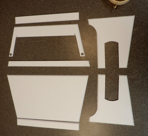 You'll also need masking tape. |
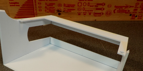
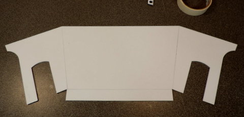 Start with the Large Side panel and arrange the two ends and the top piece with the outside up (bevels down). Alignment of the ends is critical. Tape the edges so they are in contact. 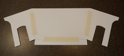 |
 |
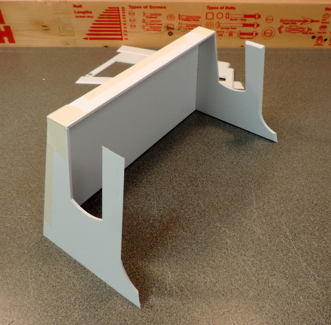 Left: Fold up the parts Above: Tape the top to the ends so that the joints are tight |
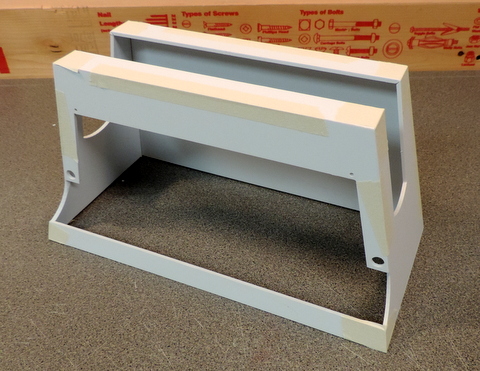
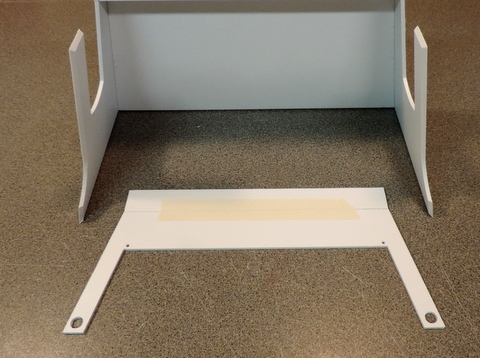 Continue with the remaining top and side panels |
 Join the top section to the previously assembled shell parts. |
 Above: Fold the edges of the tape up making sure the joint along the edges is tight. Right: Turn the shell over & fold down the side and tape. |
 |
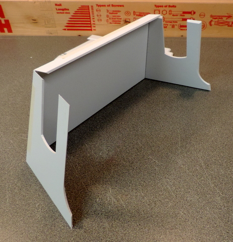
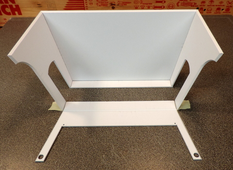
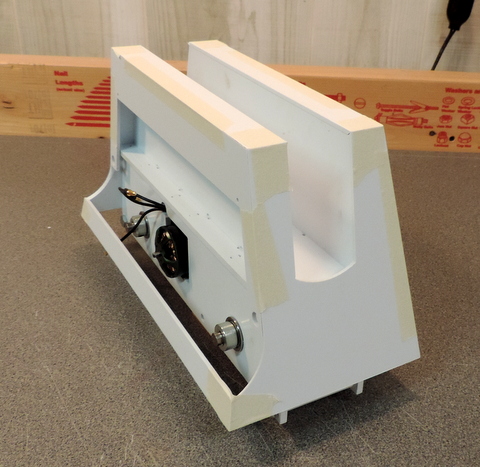
 Above: Taped up shell ready for glue up. Above: Taped up shell ready for glue up.Right: Test fitting the shell to the prototype Drive Structural assembly. |
 |
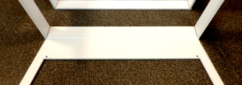
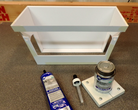 | Glue up is a two phase process. Do not attempt to rush it. First step is to use the SciGrip #3 to solvent weld the edges of the shell to each other. The edges of the joints need to be held tightly by the tape. Before applying cement inspect the joints from the inside and make sure they are tight. Notice the eye dropper. Solvent welding uses a lot of the cement. I drip it at the top of the upside down shell so that it runs down the joint. Then I add more solvent to the joints around the top piece (now at the bottom of the uside down shell). Make sure your workspace is resistant to solvent drips! Wait for the solvent to completely dry out! Second step. Remove the tape and inspect the joints. If necessary re-apply the tape and repeat the weld process. If your joints are all tight run a bead of SciGrip #16 on the inside of the joints to fill the void between the panels of the shell. Keep in mind that excess glue on the top pieces where they sit on the Drive Structural frame will keep the shell from sitting properly. |