Chopper's Head
& Rolled Flat Head Skins
Update
07/29/18 - Version 3.1 of Chopper's Head Design has been released
Update 05/15/18 -
Version 1.0 of Chopper's Head Design has been released. Published
Assembly drawings and pictures.
Update 11/05/17 - made corrections to drawings of the flat skin
sections - now marked v0.1 to reflect changes
Update 10/31/17 - 3D design work on the first prototype of a head
design for Chopper is complete.
Update
7/23/17 - The
3D solid version of the head has been
updated to
follow Cleofett's drawing more closely.
Original
Post 07/02/17 - Chopper's
Head is derived from Cleofett's .dwg drawing files
with details added from TinyP's 3D printed parts.
 |
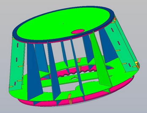 |
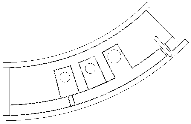
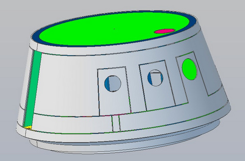
| Images above are linked
to 3D.pdf files so you can rotate/zoom in to see details. |
|
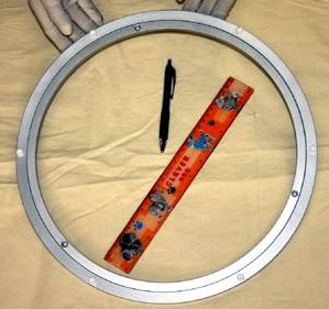 Above: This is a VXB website picture of the bearing. It's misleading, there are actually 6 holes in the inner ring. Some are blind holes. Left: I got ahead of myself and didn't take pix of the "before" version (similar to above). This is the disassembled bearing. I drilled out the holes for #10 screws and then countersunk them. Note the Markings. I added more. To re-assemble, and for alignment later on, Before You Disassemble mark inner & outer bearing races with Top & Bottom and then number the holes. From experience with R2's Rockler Bearing plan on disassembling the bearing. It's almost impossible to prevent aluminum shavings from getting into the bearing race. |
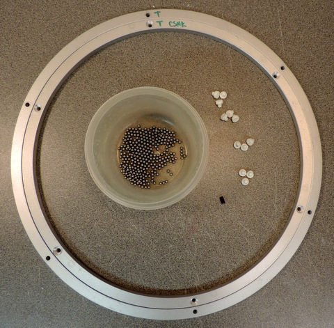 You may also want to replace the balls with Acetal ones for a smoother ride.The balls from the bearing measure 3.93mm or .1545in in diameter. You should be able to get acetal balls from McMaster Carr. |
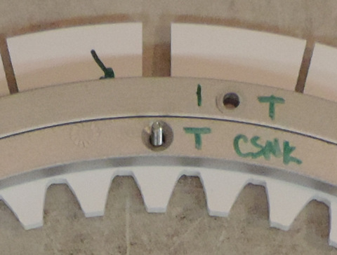
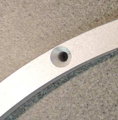 Example 1: this hole is drilled close to the outer edge |
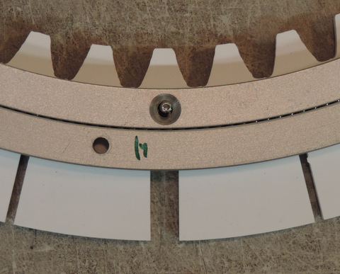
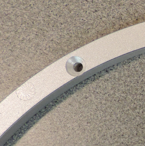 Example 2: this hole is drilled close to the inner edge |
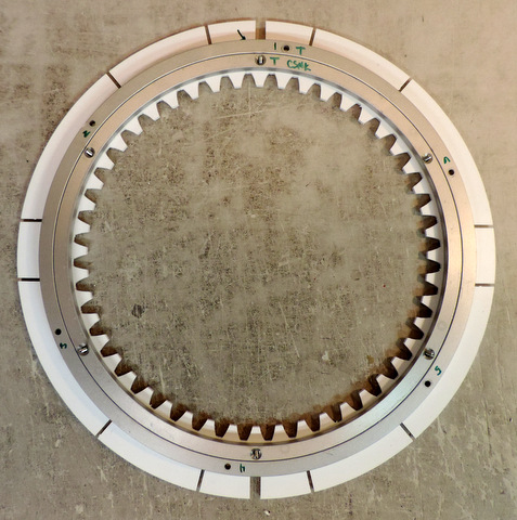
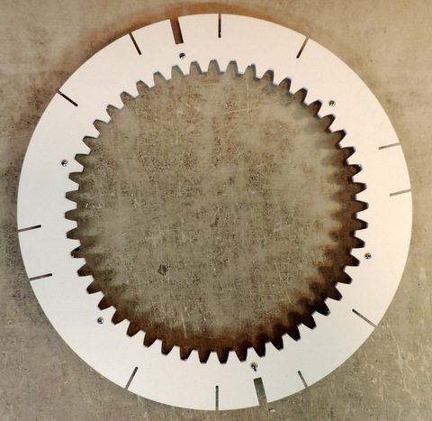 this is the Head Bottom ring I've installed 6 6-32 x 1 screws into the holes - they will cut their own threads in the plastic - no need to tap |
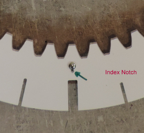 The hole indicated by the green arrow is the "front of droid" marker hole. The short slot is the one for the index rib (more later on) |
 My bearing was a tight fit onto the #6 screws - meaning that the mounting circle drilled in the plastic does not match the actual holes in the bearing. |
 this screw, like the others, is tight against the inside of the hole. |
 |
So here is one 'plan' to get alignment with the
mounting holes. First, verify that the bearing is centered on the ring. measure the tooth edge to the inside of the inner race and verify that it's the same all around. You can do the same for the outer bearing to the outside edge, just put tape on the bearing to hold it in place. Then remove just one of the #6 screws. Use the bearing as a guide and drill out the hole in the Head Bottom ring to fit #10 (Use an undersized drill with tape on it to avoid creating aluminum shavings that might get into the bearing! - remove the bearing and complete enlarging the hole to #10 clearance). Then replace the bearing on the ring, use a #10 screw in the enlarged hole. Repeat the process with the #6 screw that is on the opposite side of the circle. Then so the same for the other sets of holes. Your Mileage may Vary. This 'process' is not tested (yet). If anyone has suggestions on a better process please let me know! |